
Group 07 - Display Sniffer
![[Vídeo do projeto]](/projects/group07/logosniffer.png)
| Team: |
Group 07: Carlos Silva (Coord.) , José Martins , Pedro Barbosa , Pedro Cunha , Tomás Romano |
| Company: | Bosch Termotecnologia, SA |
| Supervisors: |
Vitor Cunha (DETI)
Francisco Pinto (Bosch Termotecnlogia, SA) |
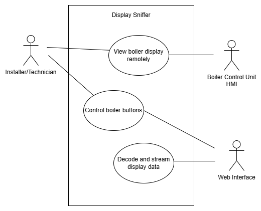
The Display Sniffer, virtualizes a boiler’s HMI by passively reading and decoding SPI display signals from the control board. It reproduces the interface in real time on a WiFi‑accessible web page and allows sending button‑like commands back to the unit. This enables full remote interaction without altering the original system, improving maintenance, usability, and flexibility.
Challenge
Modern boilers are often installed in locations that are difficult to access, making installation, commissioning, monitoring, and maintenance tasks inefficient and time-consuming. Technicians must rely on direct physical access to the display and buttons, which can be impractical in the field. Additionally, existing systems were not designed to provide remote visualization or interaction, and modifying the original hardware or firmware is undesirable due to certification, reliability, and cost constraints. The main challenge is therefore to enable remote access to the HMI without altering the original control system.
Solution
Here, all aspects of the implemented solution will be presented, along with detailed explanations of each component (architecture, hardware, frontend, backend). This section provides the necessary context to understand how the solution was developed and how its components interact with each other.
Architecture
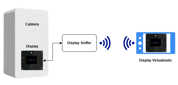
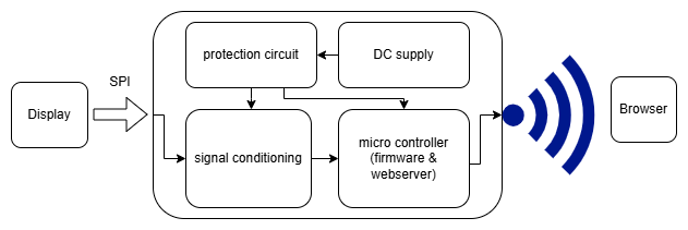
The display sniffer interfaces with both the display and a browser. It accomplishes this by using an ESP32 to read and decode data coming from the SPI lines. Its main modules can be divided into - Hardware, Backend and Frontend. The hardware encompasses the physical and electronic aspects of the system, the backend controls the sniffer system and deals with the proper decoding of the incoming data while the frontend deals with sending this data and properly displaying it on a web interface.
Hardware
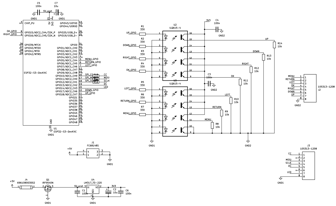
The developed hardware aimed to integrate the ESP32, protection circuits, signal conditioning circuits, interface connectors, and a mechanical structure (enclosure) in which the PCB can be safely mounted, resulting in a physical and functional prototype ready to be used by a technician or engineer in an industrial or home environment. The hardware is powered by a 5 V, 2 A DC power supply.
The microcontroller is an ESP32-S3 DevKitC-1 N32R16, with a 240MHz CPU clock speed, 32MB of flash memory and 16MB of PSRAM. It also contains 2 CPU cores that are very useful for running real time signal acquisition in one core while the other deals with image processing and web server tasks.
The power protection circuit was designed to protect against reverse polarity, overcurrent, and overvoltage conditions and is composed of a fuse, a PMOS transistor operating as a diode, and a voltage regulator. Its maximum input limits are 1 A, 15 V, −20 V, with a maximum average power consumption of 2.5 W (5 V at 0.5 A). Overcurrent protection is implemented using a fast-acting metal fuse, overvoltage protection is provided by the LDO regulator and reverse polarity protection is ensured by connecting the PMOS gate to ground, the drain to Vin, and the source to Vout. This MOSFET has a low RdsON (0.2 Ω), which, for the maximum circuit current of 0.5 A, results in a forward voltage drop of approximately 0.1 V.
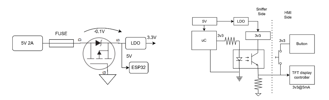
To protect the boiler side from any failure of the hardware developed by us, optocouplers were used on the lines where the microcontroller writes signals. These ensure galvanic isolation while still allowing signal transmission through optical coupling.
Signal conditioning was designed to ensure signal integrity and robustness against electromagnetic interference (EMI), particularly in long-wire connections. To mitigate these issues, termination resistors were added on lines carrying critical signals (SCLK, MOSI) to match impedances and reduce ringing effects. Pull-up resistors were also added to the lines used by the ESP32 GPIOs to control the boiler buttons, ensuring a defined logic level and eliminating antenna effects.
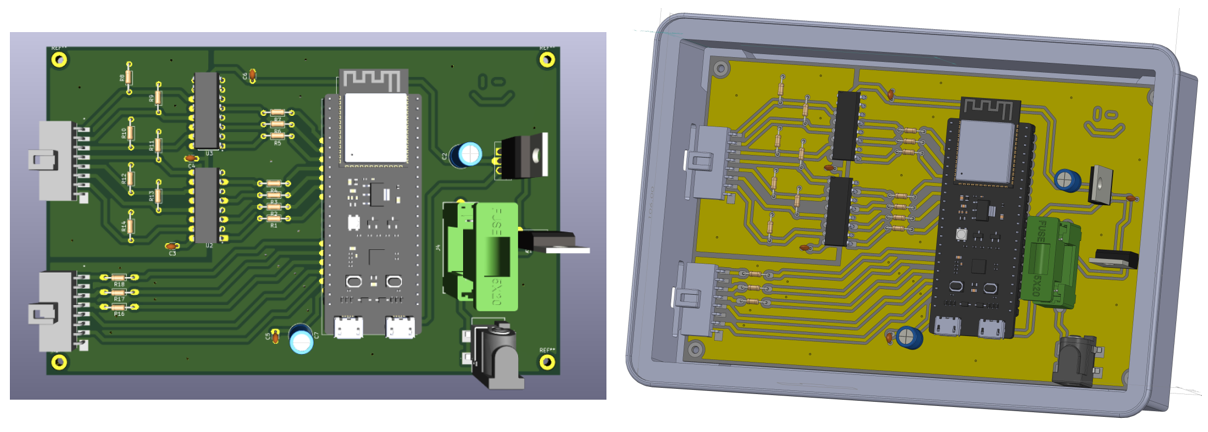
The PCB layout itself was also designed with these considerations in mind. Continuous ground planes were implemented on both the top and bottom layers, along with appropriate vias and decoupling capacitors to ensure a low-impedance return path. This strategy reduces crosstalk between signal lines and increases noise immunity. Once the PCB was finalized, the final enclosure prototype was designed to house the PCB. The enclosure has dimensions of 160 × 110 × 40 mm.
Backend
The backend of the Display Sniffer system is implemented entirely on the ESP32, which acts as a multi-role embedded platform responsible for signal acquisition, data processing, network communication, and system control. The backend integrates real-time tasks, hardware interfaces, and network services, forming the core of the system operation.
The backend follows a multitasking architecture based on FreeRTOS, allowing concurrent execution of time-critical and network-related processes. Independent tasks are used to isolate functionalities such as SPI data acquisition, web server handling, DNS redirection, and control logic, ensuring responsiveness and system stability.
Inter-task communication is achieved using FreeRTOS queues and shared memory buffers, enabling safe and efficient data exchange between real-time processing tasks and higher-level network services.
At the core of the backend is the SPI sniffer module, configured in slave mode to passively capture communication between the boiler control unit and the display driver. Incoming SPI transactions are received through DMA-capable buffers to minimize CPU load and prevent data loss at high clock rates.
The backend continuously processes received SPI packets, distinguishing between command and data transmissions using both the DCX control signal and packet length. Display control commands are decoded to determine active drawing windows, while pixel data is written directly into a framebuffer stored in external PSRAM.
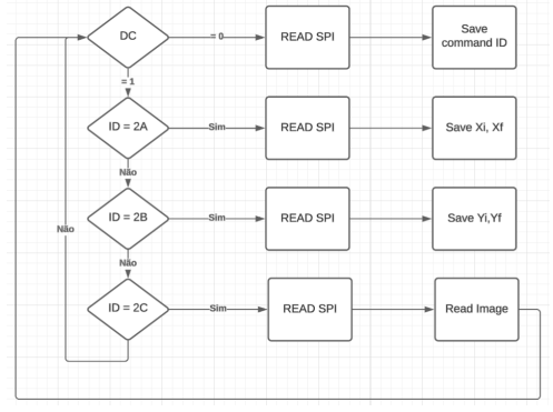
This approach enables real-time reconstruction of the display contents without interfering with the original SPI communication.
Two framebuffers are maintained by the backend:
- A live framebuffer, updated continuously as new SPI data is received;
- A snapshot framebuffer, used by the web server to serve stable image data to clients.
This double-buffering strategy prevents data corruption and visual artifacts during concurrent access by the SPI processing task and the HTTP server.
The backend includes an embedded HTTP server responsible for serving both static content (HTML, CSS, JavaScript) and dynamic data generated at runtime. Several REST-like endpoints are implemented, including:
- Image capture endpoints that generate bitmap representations of the current framebuffer;
- Control endpoints that receive button press commands from the frontend;
- Status endpoints that expose system and boiler state information.
Dynamic content is streamed in chunks to reduce memory usage and accommodate the limited resources of the ESP32.
User interaction commands received via the web interface are processed by a dedicated control task. These commands are placed into a FreeRTOS queue and translated into physical actions by toggling GPIO pins connected to the boiler’s button inputs.
Each virtual button press is emulated with accurate timing to match real user interaction, ensuring compatibility with the original HMI logic.
The ESP32 operates as a Wi-Fi Access Point, allowing direct client connections without external infrastructure. A lightweight DNS server is implemented to redirect all DNS queries to the ESP32’s IP address, enabling captive portal behavior and automatic redirection to the web interface upon connection.
This design simplifies user access and ensures that the system remains fully functional in isolated or industrial environments.
The backend carefully manages system resources to ensure stable operation:
- Time-critical tasks are pinned to dedicated CPU cores;
- DMA and PSRAM are used to handle large data buffers efficiently;
- Watchdog-friendly task design prevents system stalls;
- Memory allocation is performed during initialization to avoid fragmentation.
Despite current limitations related to SPI data stability, the backend architecture is robust and scalable, allowing future improvements in signal acquisition without requiring major architectural changes.
The backend serves as the operational backbone of the Display Sniffer system, combining real-time data acquisition, signal decoding, network services, and control logic within a single embedded platform. Its multitasking architecture, efficient memory management, and modular design enable reliable remote HMI virtualization while maintaining full compatibility with the original boiler system.
Frontend
The frontend of the system was developed to enable remote visualization and interaction with the HMI using only a standard web browser, without requiring any additional software. The interface is fully self-contained and is served directly by the ESP32S3 and running in its core 0, which operates simultaneously as a web server and a Wi-Fi access point. The web interface was implemented using HTML and JavaScript, embedded within the ESP32 firmware and delivered through an internal HTTP server. This approach minimizes system complexity, ensures platform independence, and automatically adapts to different screen sizes and orientations, ensuring usability across multiple devices.
The boiler display is reproduced on the web interface through periodic updates of an image generated by the ESP32 and accessed via the /capture.bmp endpoint. JavaScript is used to issue regular HTTP requests to retrieve the latest framebuffer snapshot. To prevent browser-side caching and guarantee that each request returns the most recent image, a timestamp parameter is appended to the image URL. The received image is then dynamically updated within an HTML element, enabling near real-time visualization of the HMI. A polling-based update mechanism was chosen due to its simplicity and reliability, as well as its compatibility with the limited computational and memory resources of the ESP32, while still providing a refresh rate adequate for human interaction.
User interaction is handled through virtual buttons implemented in HTML and managed via JavaScript event handlers. Each button corresponds to a specific HMI function, such as UP, DOWN, RIGHT, OK, LEFT, RETURN and MENU. When a button is pressed, the frontend sends an HTTP request to the /button endpoint, specifying the corresponding button identifier. The ESP32 server processes this request and triggers the equivalent physical action by driving the appropriate GPIOs high, effectively emulating a real button press on the boiler interface. This mechanism ensures functional equivalence between local and remote interaction with the HMI, without requiring any modification to the original boiler control system.
In addition to display replication and control, the frontend provides visual feedback on the system state by acquiring the state of the LED of the physical boiler and displaying it in its interface in real time.
Mitigation Plan
During the development of the project, significant difficulties were encountered in validating the values captured by the ESP32 over the SPI bus. These issues were mainly caused by variable clock rates on the bus and by synchronization challenges, despite the operating frequencies (15 MHz and 30 MHz) being well below the specified maximum of 60 MHz. Additionally, the presence of an extra control signal distinguishing data from commands further complicated reliable synchronization between signals.
To address these limitations, an FPGA-based solution was proposed to implement frame detection and to act as an interface between the boiler and the microcontroller. Thanks to its inherent parallel processing capabilities, the FPGA is able to analyze all bus lines simultaneously without the timing constraints typically associated with microcontrollers. Once a complete frame was detected, the FPGA would transmit the reconstructed frame data to the ESP32 via SPI.
In this architecture, the boiler operates in its own clock domain, while the FPGA and ESP32 share a separate clock domain. A FIFO buffer was introduced to safely bridge these domains and prevent data loss. Both the data line and the data/command indicator line are processed by a finite state machine (FSM), designed to detect valid display frames based on the expected command sequence: 0x2A (column address), 0x2B (row address), followed by 0x2C and the pixel data stream. The inclusion of timeouts and validation rules in the FSM increased robustness by preventing misinterpretation of commands as data and vice versa. Only valid frames were stored and prepared for transmission to the microcontroller.
Integrated tests with the boiler confirmed correct frame detection, which was validated through image reconstruction in MATLAB. Following FSM validation, efforts focused on establishing reliable SPI communication between the FPGA and the ESP32. Multiple tests were conducted using known data patterns in isolated environments to verify data integrity. However, communication between the FPGA and the microcontroller proved unreliable. The SPI interface was required to operate in slave mode, as the FPGA had only one available clock input, already allocated to the boiler’s SPI bus. Reducing the clock frequency did not resolve the issue and was not a viable solution, since the continuous data stream from the boiler cannot be controlled and lowering the clock would introduce data loss.
As a result, this approach was not pursued further during the transition phase. Progress with an ESP32-only implementation proved more consistent, while no satisfactory solution was achieved for the FPGA–ESP32 interface. Nevertheless, the FPGA-based prototype remains a valid risk-mitigation alternative, addressing concerns related to the suitability of the chosen microcontroller and system architecture. Although technically feasible, this approach would increase system complexity and overall product cost.
Results
The Display Sniffer project resulted in the successful development of a functional prototype capable of remotely virtualizing the Human-Machine Interface (HMI) of a consumer boiler without modifying its original hardware architecture. The solution integrates embedded hardware, real-time signal acquisition, backend processing, and a web-based frontend to enable remote visualization and interaction.
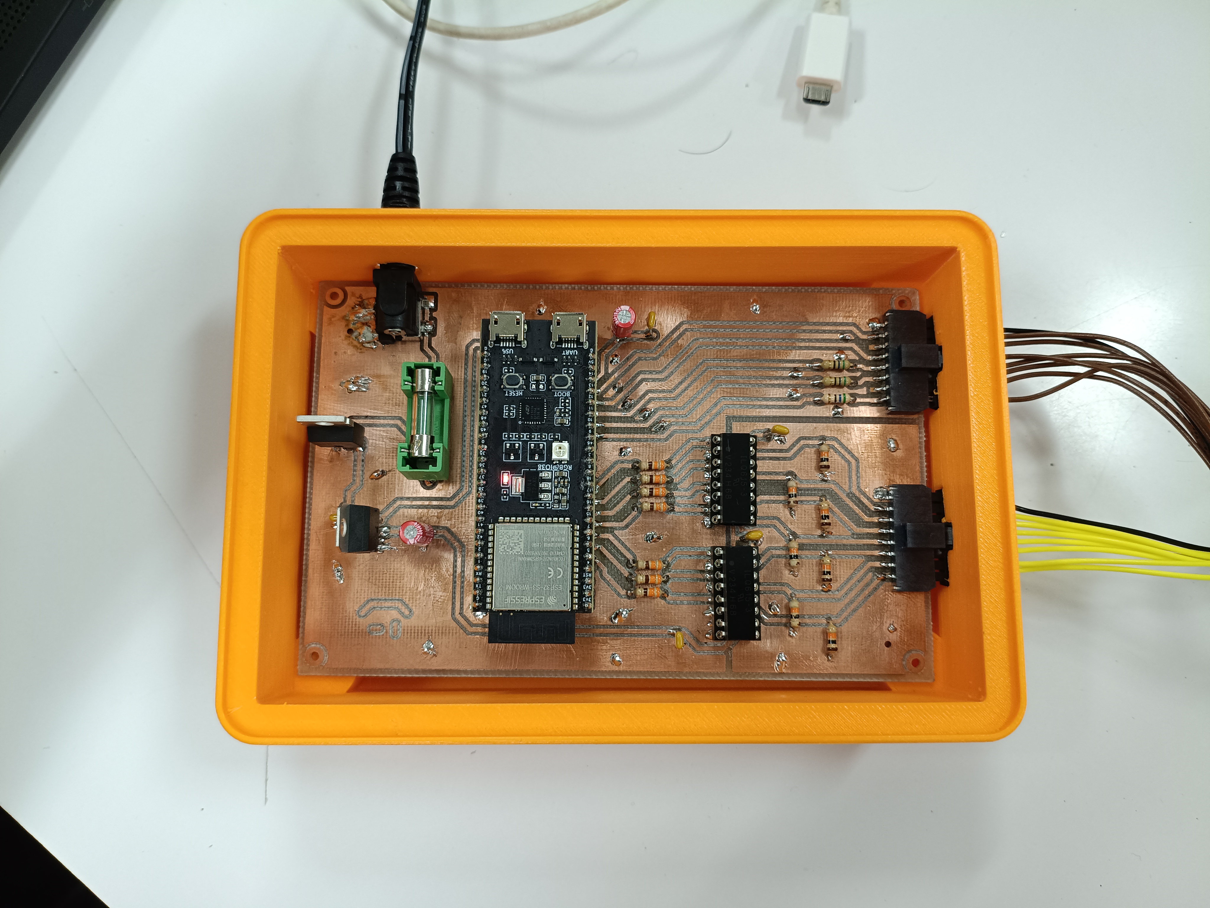
From a hardware perspective, a dedicated PCB was designed and validated, integrating the ESP32 microcontroller, power protection circuits, signal conditioning, galvanic isolation through optocouplers, and standardized interface connectors. The hardware operates reliably from a 5 V DC power supply, within the defined current and power limits, and demonstrated adequate robustness against electrical noise and polarity or overvoltage faults. The mechanical enclosure further allowed the creation of a safe, portable, and usable prototype.
At the firmware and backend level, the system captures SPI display traffic in real time using DMA-based SPI slave operation on the ESP32. The backend correctly decodes display commands and pixel data and reconstructs framebuffer segments according to the detected display protocol. The implementation demonstrates that it is technically feasible to non-intrusively monitor a high-speed SPI display interface using a microcontroller-based solution. However, results also showed that signal integrity, synchronization issues on the SPI bus and unknown errors in the decode software can lead to partial frame reconstruction, limiting continuous and fully coherent display replication.
Despite these limitations, the backend infrastructure proved operational: raw SPI data could be received, processed, and forwarded to higher software layers. The system architecture, based on FreeRTOS task separation and DMA-driven acquisition, effectively isolated real-time data capture from network-related tasks, validating the overall design approach.
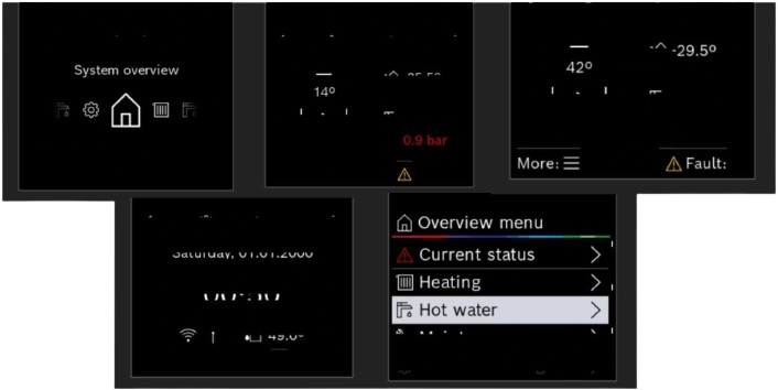
On the software side, a complete web-based interface was implemented and validated. The server and client logic correctly handle data transmission, automatic updates, and visual adaptation. Fragmented image segments received from the backend were successfully displayed in the browser, confirming the correctness of the data flow from acquisition to presentation. Additionally, remote interaction with the boiler HMI through the web interface was fully functional, allowing a user to emulate button presses and control the system at distances of up to 20 meters, limited by Wi-Fi coverage.
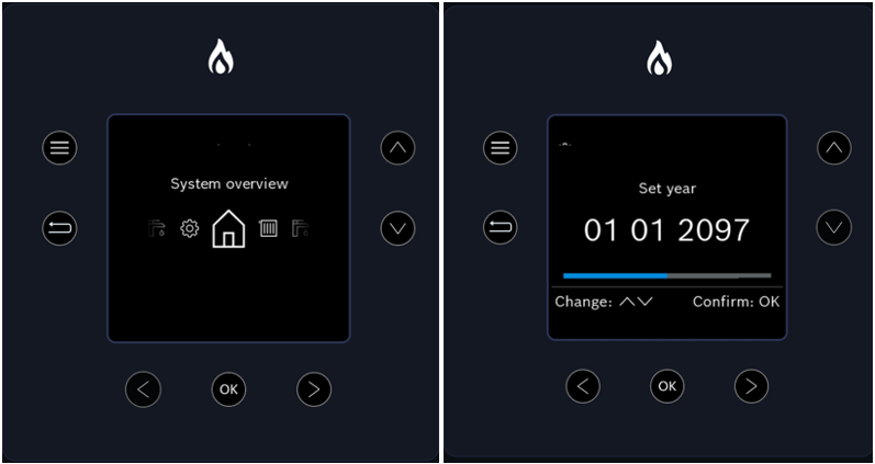
An alternative FPGA-based approach was also partially validated. Frame detection using a finite state machine implemented in FPGA logic was successfully tested and confirmed through MATLAB-based reconstruction, demonstrating accurate identification of valid display frames. However, reliable SPI communication between the FPGA and the ESP32 could not be achieved within the project timeframe, preventing full integration of this solution. As a result, the FPGA approach was not adopted in the final prototype, although it remains a viable option for future iterations where higher robustness and determinism are required. To the students, this project delivered practical experience in project management, embedded systems design, communication protocols and hardware and software design, as well as product validation and testing, aligning closely with real industrial requirements. In summary, the project achieved its main functional goals by demonstrating a working end-to-end system for remote HMI virtualization. While full continuous frame replication was not attained due to backend signal stability constraints and/or data decoding errors, the results validate the feasibility of the proposed concept and establish a solid technical foundation for future improvements and industrialization.
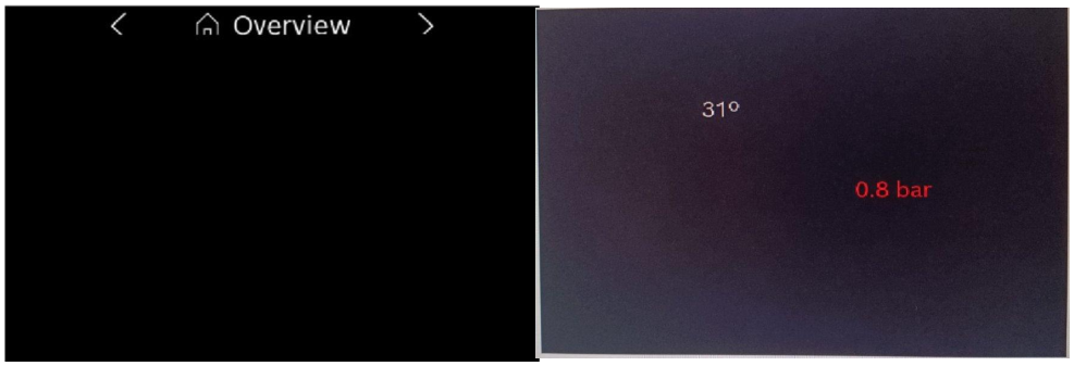
Below, we show a video of project functionality